First, you need to disconnect the LED light.
Remove the four bolts that secure the roof. After that, remove the roof and place it to the side of the roaster.
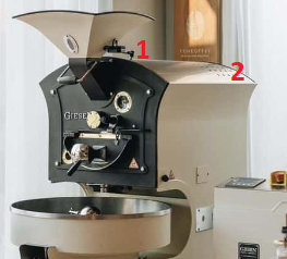
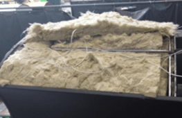
Move the insulation a little on the ceiling to find the cable of the PTt100, for this we suggest using gloves.
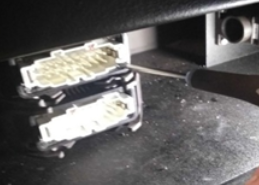
Disconnect the top left plug off the machine. This is connected to the control panel. These connectors are located at the back of the machine in the bottom.
Remove the 4 screws so that you can take out the terminal.
Remove the wires by pressing the orange button with a small and flat screwdriver while gently pulling on the wire.
This step is only for bean sensor:
Remove the bolts securing the old sensor and remove it from the tube. For older machines, it is connected with 1 allen screw, while newer machines use 2 allen screws.
This step is only for bean sensor:
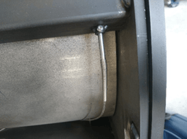
Pass the cable of the new sensor through the tube and secure it with the bolts, then connect it to the rear connector. Don’t forget to put the spring around the wire.
This step is only for air sensor:
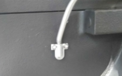
Locate the air sensor on one side of the insulation, and then remove the screw holding it. It is important to install the new sensor at the same level as the old one. This can be achieved in several ways, such as marking the position of the old sensor and placing the new PT100 next to it, ensuring it is marked at the same height to provide a reference when installing the new PT100. Next, pass the cable between the insulation and connect it to the rear connector.
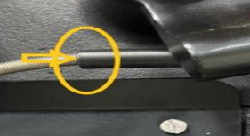
When you have already inserted the cable into the rear connector, proceed to remove only the plastic caps and metal parts of the new sensor (only the one marked in yellow) using pliers.
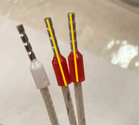
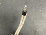
Now connect the copper wires at both ends to attach them to a new cap.
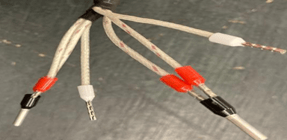
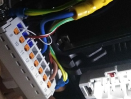
It should look like this:
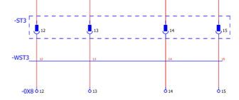
One set of wires should be connected in position 12, while the white wire should be in position 13. The other set of wires should be connected in position 14, and the white wire should be in position 15.
11. You can replace the roof, and remember to connect the wire for the light.